
Modeling features in RISAConnection may be accessed through the ribbon toolbar, shortcut keystrokes, and the Connection Properties spreadsheet. You may use any or all of these options to interact with the software. The ribbon toolbar contains the tools required to create new models, save, print, access Global Project Settings, and the viewing options. The shortcut keys provide a fast way to access features should you use the program often enough to make them familiar to you. Finally, the Connection Properties spreadsheet contains all the user-input data to model your connection. These features are discussed in the sections below.
The bar at the top is called the title bar. The title of your project can be seen in the center of the bar, and the buttons are described below:
| Button | Function |
|---|---|

|
Starts a new project |

|
Opens a previously created project |

|
Adds a connection to the current project |

|
Saves the current project |

|
Prints the current connection view |

|
Access the report printing options |

|
Undo previous changes |

|
Redo previous changes |

|
Minimize program window |

|
Maximize program window |

|
Restore down the program window |

|
Close the program |
Just beneath the title bar is the ribbon toolbar. This toolbar is divided into tabs to combine similar features and tools. Each tab is described below.
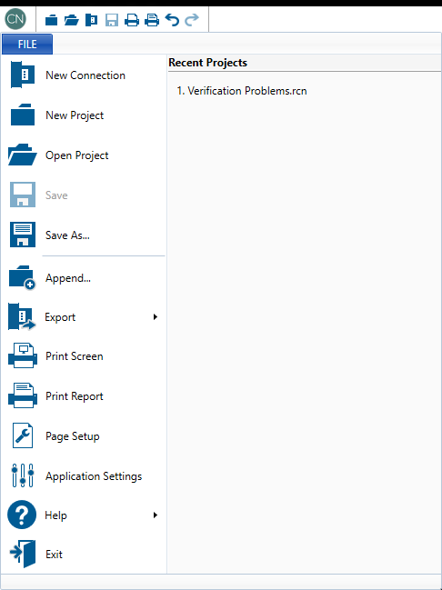
The File menu contains the same model options as the Title bar (New, Open, Save, Print) with a few more. The additional functions are described below.
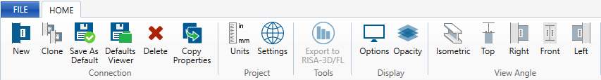
The Home menu contains some global buttons which effect the whole project and some buttons which are only applicable to whichever view you are in. For example, when you are in the 3D View, the Home menu will contain options for the view angle of the connection, and when you are in the 2D View, the options for toggling the loads, dimensions, and bolts become available.
The buttons are described below:
| Button | Function | 3D View | 2D View | Reports |
|---|---|---|---|---|

|
Add a new connection to the project. |
x | x | x |

|
Copy the selected connection. | x | x | x |

|
Save connection geometry and input as the new default for all future connections. | x | x | x |

|
Opens the defaults viewer dialog box. | x | x | x |

|
Delete the selected connection. | x | x | x |

|
Copy the properties and configurations of selected connection to other applicable connections. | x | x | x |

|
Access the Units dialog. | x | x | x |

|
Access the Global Parameters. | x | x | x |

|
Export the connection results to RISA-3D or RISAFloor (for integrated models only). | x | x | x |

|
Export the connection results to Tekla Structures (for integrated models only). | x | x | x |

|
Access connection display options. See Graphic Display for more information. | x | x | x |

|
Toggle an opaque or transparent view. | x | ||

|
Toggle the view of the bolts on or off. | x | ||

|
Toggle the view of the dimensions on or off. | x | ||
|
|
Toggle the view of the loads on or off. | x | ||

|
Toggle the view of the Whitmore Section and unbraced length (applicable to vertical braced connections only) | x | ||

|
Snap to isometric view. | x | ||

|
Snap to top view. | x | ||

|
Snap to right view. | x | ||

|
Snap to front view. | x | ||

|
Snap to left view. | x | ||

|
Copy the top gusset geometry to the bottom gusset (for Vertical Brace Diagonal Connections only). | x | x | x |

|
Copy the bottom gusset geometry to the top gusset (for Vertical Brace Diagonal Connections only). | x | x | x |

|
Solve all connections in the project (for integrated models only). | x | x | x |

|
Solve all connections in the group (for integrated models only). | x | x | x |

|
Solve just the selected connection (for integrated models only). | x | x | x |

|
This button allows you to access the HTML5 help menu, check for updates, and view the About Connection page which contains version and licensing information. | x | x | x |
The following keys (or key combinations) can be accessed as shortcuts to help speed up your modeling.
| Shortcut Key | Action |
|---|---|
| CRTL + O | Open a File |
| CRTL + S | Save a File |
| F1 | Access Help Menu |
| F2 | Switch to a 2D View |
| F3 | Switch to a 3D View |
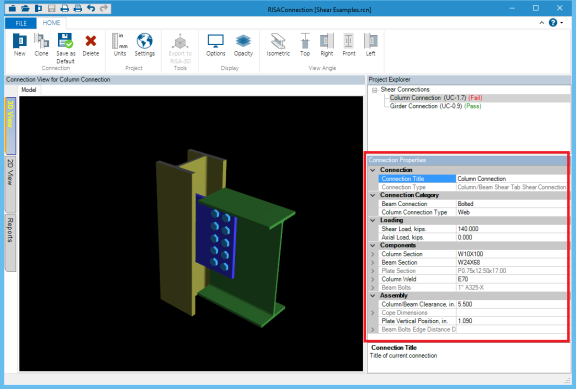
The Connection View provides options for viewing both the graphical display of the connection (in 2D or 3D view) and also viewing the result output report.
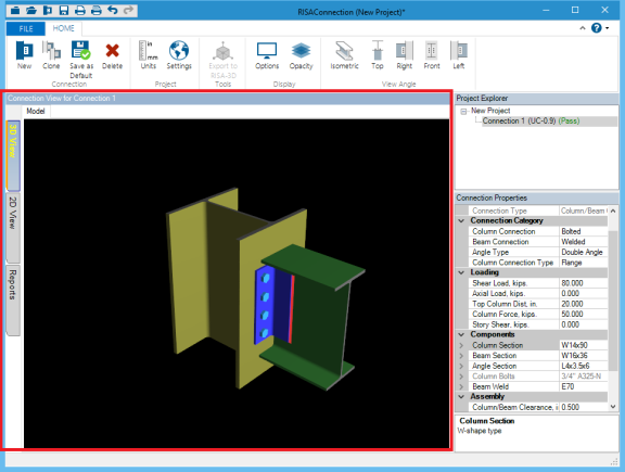
Graphical Display
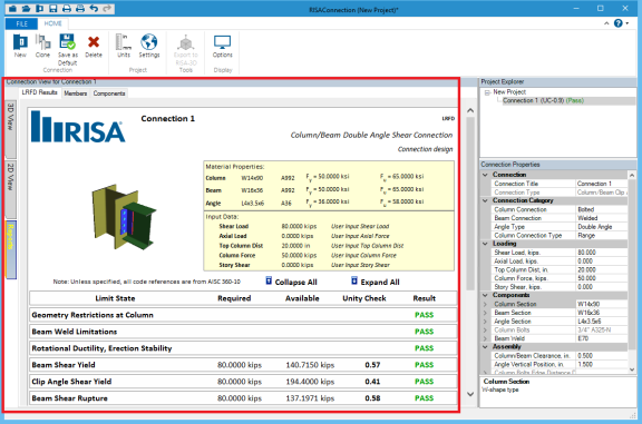
Results Report
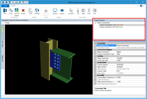
This view allows you to move your connection around and view it from all sides and angles. If you click on a specific connection element in this view it will highlight in the Connection Properties section. See the Graphic Display topic for more information.
Viewing the model in 2D allows you to see each of the components of the connection, complete with dimensions, bolt holes and some assembly views.
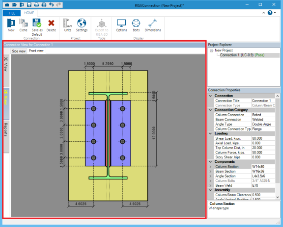
If you click on a specific connection element or dimension, that element or dimension will highlight in the Connection Properties section. See the Graphic Display topic for more information.
Certain views in the 2D view can visually show the loads applied to the connection, enhancing clarity and customization during design reviews and presentations.
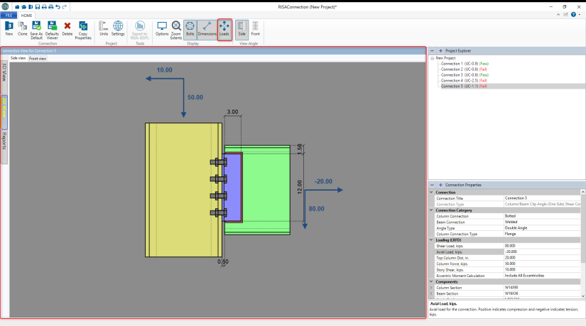
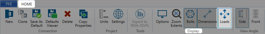
This feature can be turned on by clicking the Loads button in the Home menu as shown below.
The Reports section shows all the results from the program, including component properties and design checks. See the Graphic Display topic and the design checks topics for more information.
The Project Explorer shows the current project along with a list of all the connections in the project file.
The Connection Properties gives ability to define all of the parameters for the connection. Modifying this data automatically updates the design check calculations in standalone mode. If integrated with RISAFloor and/or RISA-3D, then you must re-solve the connection after changes.
Note:
The Connection Title allows you to give your connection a specific name. The Connection Type gives a quick description of the components of the connection.
The Seismic Detailing section allows you to assign seismic parameters to your connection. This is only applicable to the following connection types:
For more information, see the Seismic Detailing topic.
The Connection Category allows you to define the connection type (bolted vs welded) and orientation.
Beam Connection allows you to choose a Welded or Bolted connection.
Column Connection Type will only be available when the column is a rectangular HSS tube where you have the option to connect the beam to the Wide or Narrow face of the column.
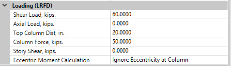
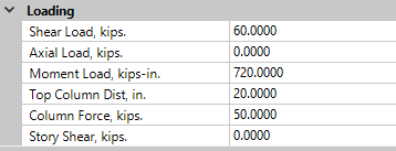
This is the location where you define the loading on your connection. For shear connections, you will define the Shear Load and the Axial Load (if applicable), which are simply the shear and axial demand for the connection. Positive axial loads designate compression loads, and negative axial loads designate tension loads.
Note:
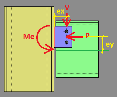
The Eccentric Moment Calculation input allows the user to control the eccentricities used to calculate the moment due to eccentricity at the connection.
Note:
For moment connections you will also define the Moment Load which is the required demand for the connection.
In addition to these, there are some extra inputs described below.
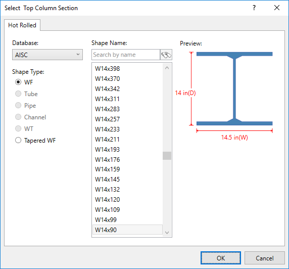
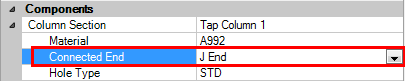
The Components section is a location where you can input specific details about the different connection components. This is where you define member sections, materials, bolt information, weld information and other specifics. Most of these items are self-explanatory. Here are some details of the inputs.
In the Shape Selection dialog you can choose which shape Database you wish to use. This allows access to all of the RISA foreign shapes databases. Note that RISAConnection will NOT read in shapes from the AISC_BACKUP database.
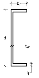
Channel members are available to be used as beam and brace members in the shear connections. Channel shapes are not currently available for moment connection members. When a channel shape is selected, the connector will always be attached to the back (web) of the channel section.
Note:
RISAConnection will allow you to select a tapered WF shape for some members in some connections. Please see below for a list of available members.
Limitations:
k_des = t_flange
k_det = t_flange
k_1 = 0.5*t_web
k = t_flange
When clip angle connections are not symmetric, the leg orientation will be specified as:
| Angle Orientation | Explanation |
|---|---|
| LLS | Long Leg Supported (or Short Legs Back to Back) |
| SLS | Short Leg Supported (or Long Legs Back to Back) |
The following table shows the different types of available hole types:
| Hole Type | Explanation |
|---|---|
| STD | Standard holes |
| OVS | Oversize holes |
| XOVS | Extra Oversize Holes (applicable to Base Plates only (per AISC 360-10 Table C-J9.1) |
| SSLH | Short-slotted holes with the long dimension horizontal. |
|
SSLV |
Short-slotted holes with the long dimension vertical. |
| LSLH | Long-slotted holes with the long dimension horizontal. |
| LSLV | Long-slotted holes with the long dimension vertical. |
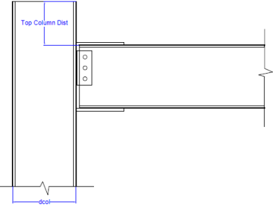
The Assembly section is where you define other required dimensions such as: coping dimensions, edge distances, clearances, etc. Many of these values can be changed manually. Some of these values have maximum values that if you exceed that value we will use the maximum value. Other values are grayed out, meaning their value is dependent on other dimensional properties of the connection.
Notice that for all of the input, a more detailed explanation will be displayed in the display at the lower right corner of the screen.
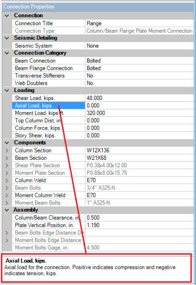
Try clicking around in the various input cells to see this display change.
Here are some specific assembly details.